About the different models:
The Peavey 5150 should need no introduction.
The 5150II is a 5150 with an improved clean channel, and a modified distortion channel. It also has a different power supply and a few changes in the power section. You can’t make a 5150 sound like a 5150II or vice versa without severe modification, but you can get them a bit closer by some simple mods.
Later, the 5150 was relaunched as the 6505, and the 5150II as the 6505+. They made no changes to the circuit at this point. If a 5150 sounds different from a 6505 it’s due to different tubes, or the age of the components, not a change in design.
The 5150 2×12 combo is different from both the 5150 and the 5150II. Tone-wise it’s said to be somewhere between the two, but I don’t know this circuit.
The 6505+ 112 combo has a preamp nearly identical to the 5150II, but a new fx loop and power amp.
Make your 5150II sound more like the original 5105
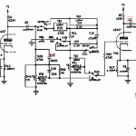
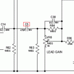
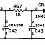
 This mod will make changes to the preamp section to make the ultra channel of your 5150II match the specs of the original 5150. This without affecting the clean/crunch channels. Your amp will be be growlier, more organic, more gainy and get a chunkier attack, but it will also become less tight. It will not sound 100% like the 5150, as there are some differences in the fx loop / power amp stage as well, but it will take it in the right direction. |
|
| This mod is also applicable to the 6505+ 112 combo, but the component names differ.
5150II head: 6505+ 112 combo: |
Mod the 5150/6505 lead channel to match the specs of the 5150II/6505+
You will get a more twangy top end, more fizz, not as much of a raw growl to it, and a more processed feel/sound overall. If this is what you want, do the opposite of what’s stated above.
Bias Mods:
6505+ 112:
it is possible. I recently got an email from a man called Brian Mangan, saying that you can adjust the bias of this amplifier by altering the value of R14. I have not taken the time to check the schematic or try it myself yet.
EQ Mods:
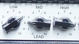
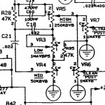
| OPTION1: Shift the mid frequency downward This is a very simple mod which will move the focus point of the MID band to a lower frequency. 5150/5150II: 6505+ 112: OPTION2: Make the mid frequency sweepable 5150: 6505+ 112: |
Other preamp mods:
I found these mods in the Rig-Talk forum, and they were originally posted by Mark Cameron. They are designed for the original 5150, and may or may not work well with the 5150II or combo versions:
V5B(middle preamp tube): add 10pf silver mica cap to pins 7 and 8. This will remove hiss, make the gain less fizzy, make the high mids clearer and improve clarity in chords. between pins 6 and 7 it’s even more efficient, but will also darken the amp a lot.
R9: piggyback a resistor on top of the 1 meg resistor. 120k is a good starting point. You can try out 68k, 100k, 120k, 150k, etc. Lower value means tighter amp, but if you go too low, the amp will be choked out.
C26: cut one leg for less bottom end on the rhythm channel
C15: bypass cap for better “feel”
R22: bypass for better dynamics and clearer picking response
I tried tinkering with R15 and using Marshall values, but it took too much away from the original sound. The 39k is the SLO value as well.
Power amp mods:
replace screen resistors (with 1k 5W)
add choke somewhere. I have to study these further. To be continued.
Credits:
I didn’t figure all of this out by myself. I’ve gathered some of this information from forum threads, and here are some of the sources:
http://www.mrbobo.com/music_5150_mods.htm (5150 bias mod and tone stack mod1)
http://www.ultimatemetal.com/forum/backline/596150-5150-mod-thread.html (EQ mod 2 + etc)
combo has a preamp nearly identical to the 5150II, but a different fx loop and power amp.

Any progress on the bias mod for 6505+ 1×12? Thank you for posting this page!
@Mr. Papa
Thanks for your interest! This summer has been very busy, and this project is one of those that had to wait. I still intend to make up a design and do the modification, but I have no clue when.
Hi, for the 2×12 combo not exist this mod?
Hi, I have not looked at the schematics for the 2×12 schematic. The mods should be possible on the 2×12 combo as well, but at this point I’m not familiar with the circuit.
i did these mods on my 6505 112. specifically the 5150 mods . and let me say i love the tone alot more. than before. however specifically when i swiched c 26 the amp got much quieter with the same volume on my post gain knob. however i can still get really loud . just seems like i have to push the post gain much higher to get the same oomph. before i never had to play past 4 or so now i have to push it up 5 or 6 . once again though killer tone
Hey on the 6505+ 112 is there a FX loop mod it sounds awful when I use pedals a guy said something about putting a Resistor solder to the fx input my guitar tech said if I found a diagram he will do it or a lnk.
Good to hear! Honestly, I haven’t got around to doing any mods to the 112 myself. What surprises me is that you now have less gain than before. My 6505 head certainly has more gain than my 6505+ 112 combo (different tubes though, that might make a difference here). Anyway, there should still be plenty of gain. If it improved your tone, all is well in my opinion 🙂
So far I’ve only used the fx loop on the 112 for plugging in other preamps, bypassing the 6505+ preamp. So, I was not aware of this problem. The fx loop is not the same as the original design, but I don’t remember how much they differ. I don’t have time to look into this right now, but let me know if you find a solution, and I’ll include it in this write-up.
Audun
I M LOOKING FOR A MOD THAT MAKE THE CLEAN/RHYTHM CHANNEL OF MY 6505+ 112, SOUND LIKE THE 5150II CLEAN /RHYTHM CHANEL WHEN THE BRIGHT SWITCH IS ENGAGED. THERE IS SOMETHING LIKE THAT?
I do not have either amp here right now, but I have brought my 6505+ 112 to the workshop at work to have a look at a problem with the fx loop, and perhaps do some of the mods I mentioned here.
I’ll look into what you’re asking about when I have the schematics in front of me. I was under the impression that the preamps were pretty much identical, but there might be a difference on the clean channel. You might try and compare the schematics yourself too. They’re not very hard to read 🙂
FX loop fix is put a .022uF (Microfarad) capacitor in parallel with R86.
Thank you for all this information!
I really need some help with the 6505+ 112 Bias Mod.. :\ Have you made any progress with it?
Any news on the 6505+ 112 bias mod?
Hi Boda, thanks for your interest. I’m sorry but right now I have my hands full with other projects, and I don’t see myself getting back to this in the near future. If you figure it out, feel free to let me know how it’s done and I’ll add it to this guide.
Audun
By Enzo:
“R108 and R14 form a voltage divider. If it were mine, I’d increase R108 to maybe 10k. That will allow more range. Then I’d replace the 220k R14 with a resistor and pot wired in series. Thus making a variable resistance. I’d experiment, but seems to me R14 could be replaced by a 50k pot wired as variable resistor and a 150k resistor. Or a 100k pot, really not critical.”
Hey boda, where did you get that info from?
I want to add a bias pot to my combo.
Hi Jeff, I’ve found that info at peavey.com forums.
Looking at the schematic you can confirm that R14 and R108 form the Bias Voltage Divider.
I’ll mod my 6505+ 112 today and post the results.
It’s confirmed. It works like a charm. You only have to replace the 220k R14 with a 1/4W resistor and potentiometer in series. The more the resistance, the colder the bias.
The matched tube pair I used (SOVTEK WXT+) was running too hot (+/- 50mA), so I used a 56k resistor plus 250k pot in series for R14, and a 10k resistor for R108. lowering the tube bias to 38mA.
Boda
Could you explain your wiring of resistor & pot? Would the 1st terminal of the pot get grounded, the resistor go to terminal 2 on the pot, and terminal 3 go back to the board?
I have an old peavey combo in my shop right, there are no Screen resistors at all! they left them out! the board is riveted onto the chassis on the octal socket mounts,very cheaply done. I’ll have to cut the traces to the screen pins and add a 1K@5watt 1% cement resistor to each socket pin 4. Also if you want to run EL34, E34L, or KT77 tubes then pin1 will have to be connected to pin 8, i believe that pin 1 is not connected to anything on this particular board so a simple jumper will work, i”ll have to check with peavey whether or not the 6.3 vac has enough juice to power that family of Pentodes, the 6L6 family requires less filament current. that power xformer can burn out. a choke can be added to the power supply i u remove power resistor between plate and B+ switch going to the screen circuit. if that power resistor is less than 1K then a 1K @5watt should be installed replacing that original value without a choke – it won’t be needed. if u got questions send an Email