About this section:
I made this section to share some electronics projects. At the time of writing I was a hobbyist in this field, and I’m keeping this online only because I have seen my content referenced on message boards etc. and I know some people are finding this content useful.
Disclaimer:
These mods and projects have worked well for me, but copying my work is at your own risk. I do not guarantee for any of the information on this site to be correct or safe.
Exposed wires and electronics can kill you, even when not plugged in. Read up on the relevant safety precautions and be careful. I take no responsibility for any form of damage or injury caused by following instructions found on this page.
Porsche 944 S2 / 968 Throttle body rebuild
I'm posting this here hoping to save someone else some time. I found most of this from the link below, by a strike of luck - the article is in German and does not show up in google search results.
The 944 throttle body tends to develop a vacuum leak at the butterfly valve axis seals. Replacing the old seals with o-rings is possible, but not the right solution. The original seals are radial lip seals and replacing such seal with an o-ring may work for a while, but this is not the correct solution.
The correct way is to replace the entire bearings, which include the seals.
The original bearing (INA F-95775) is no longer available - or perhaps it was never sold commercially. The current equivalent is the HK 0810 RS. The HK 0810 RS has a single side seal, like the original part. The HK 0810 2RS has dual seals and can be seen as an upgrade over the original parts.
These bearings are readily available from a number of different manufacturers.
The large o-rings should be replaced while the throttle body is off the car. I tried looking up cheaper replacements, however the original Porsche parts are actually reasonably priced - no reason to go aftermarket for these.
Part numbers:
Round seal 82 X 2,5 - 999 707 036 40
Round seal 65 X 3 - 999 701 331 40
There is also an o-ring at the TPS, that you may want to replace while you're in there. I will update this post when I have found the correct replacement.
Disassembly is mostly straight-forward. The hard part is removing the bearings. An M6 expanding brass anchor can be used to remove the old bearings (see link below).
These look suitable (M6 version): https://www.aliexpress.com/item/1005003512118808.html?spm=a2g0o.cart.0.0.35ff38datIqRmb&mp=1
When reassembling, the throttle plate screws must be secured. This can be done either by using split end screws or by using a high temperature thread locker.
The 944 NA and Turbo throttle bodies differ slightly (I believe one of the bearings is already a dual seal one) but as far as I know, they use the same bearings.
Removing the throttle body will let air into the coolant system, so the coolant system should be bled after the first test run, in case air bubbles have collected in the cylinder head. I also recommend a pressure test, to verify that there is no external or internal coolant leaks after mounting the rebuilt throttle body.
Source: https://www.stinni.de/index.php/porsche/drosselklappe
Porsche 944 sunroof electronics
I've had some issues with my Porsche 944 sunroof. Clarks Garage has good instructions for the mechanical issues, but at the electrical side it falls short. I'm posting my findings so far:
Please go through the guide in Clarks Garage FIRST. I'm not covering any of the areas that he already covered.
The relay:
The relay pin numbers do not correspond to the pin numbers in the socket.
relay socket pin -> relay pin
1 -> 2 (sunroof SW pin1)
2 -> R (IGN lock via F36)
3 -> 30 (Positive via F8)
4 -> A (cruise control pin1)
5 -> 1 (passenger door pin1)
6 -> 15 (from instrument panel IIRC...)
7 -> 31 (GND)
8 -> 3 (Sunroof SW pin2)
9 -> 4 (sunroof SW pin5)
Checking for voltages in the relay socket:
Pin7 is GROUND
Pin3 is always +12V
Turn the key one click and get +12V to pin2
Turn the key one more click and get +12V to pin6
I believe pin5 gets 12V when the car is locked (haven't checked)
I believe pin4 gets 12V when the car is moving (haven't checked)
If these voltages do not show up you have a problem with wiring, a blown fuse or a problem with your ignition switch.
bench-testing the relay:
In this case I'll refer to the numbers printed on the relay itself.
ground to pin31 , 12V to pin30. Check all remaining pins for voltage, you should have none.
Add +12V to pin R, you're supposed to get voltage at pin8 - I got +10V, and I don't know if you should be getting 10 or 12.
Add +12V to pin 6 (15 at the relay) +10V disappears from pin3 and +12V appears at pin2
I believe adding 12V to pin 1 or A should give +12V at pin9, but I'm not sure of wether it should affect (remove) any voltage to pin 8 or 2. I believe what this does is tell the motor to lock the sun roof in place if the car is moving or is locked. I'll update this when/if I figure out mine.
Peavey 5150 / 6505 series mods
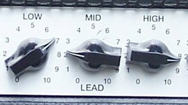
About the different models:
The Peavey 5150 should need no introduction.
The 5150II is a 5150 with an improved clean channel, and a modified distortion channel. It also has a different power supply and a few changes in the power section. You can't make a 5150 sound like a 5150II or vice versa without severe modification, but you can get them a bit closer by some simple mods.
Later, the 5150 was relaunched as the 6505, and the 5150II as the 6505+. They made no changes to the circuit at this point. If a 5150 sounds different from a 6505 it's due to different tubes, or the age of the components, not a change in design.
The 5150 2x12 combo is different from both the 5150 and the 5150II. Tone-wise it's said to be somewhere between the two, but I don't know this circuit.
The 6505+ 112 combo has a preamp nearly identical to the 5150II, but a new fx loop and power amp.
Make your 5150II sound more like the original 5105
Mod the 5150/6505 lead channel to match the specs of the 5150II/6505+ You will get a more twangy top end, more fizz, not as much of a raw growl to it, and a more processed feel/sound overall. If this is what you want, do the opposite of what's stated above.
Bias Mods:
it is possible. I recently got an email from a man called Brian Mangan, saying that you can adjust the bias of this amplifier by altering the value of R14. I have not taken the time to check the schematic or try it myself yet.
EQ Mods:
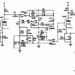
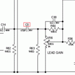
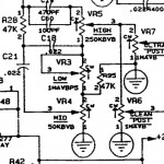
I found these mods in the Rig-Talk forum, and they were originally posted by Mark Cameron. They are designed for the original 5150, and may or may not work well with the 5150II or combo versions:
V5B(middle preamp tube): add 10pf silver mica cap to pins 7 and 8. This will remove hiss, make the gain less fizzy, make the high mids clearer and improve clarity in chords. between pins 6 and 7 it's even more efficient, but will also darken the amp a lot.
R9: piggyback a resistor on top of the 1 meg resistor. 120k is a good starting point. You can try out 68k, 100k, 120k, 150k, etc. Lower value means tighter amp, but if you go too low, the amp will be choked out.
C26: cut one leg for less bottom end on the rhythm channel
C15: bypass cap for better "feel"
R22: bypass for better dynamics and clearer picking response
I tried tinkering with R15 and using Marshall values, but it took too much away from the original sound. The 39k is the SLO value as well.
Power amp mods: replace screen resistors (with 1k 5W) add choke somewhere. I have to study these further. To be continued.
Credits: I didn't figure all of this out by myself. I've gathered some of this information from forum threads, and here are some of the sources:
http://www.mrbobo.com/music_5150_mods.htm (5150 bias mod and tone stack mod1) http://www.ultimatemetal.com/forum/backline/596150-5150-mod-thread.html (EQ mod 2 + etc) combo has a preamp nearly identical to the 5150II, but a different fx loop and power amp.
Motherboard Repair
Like most consumer electronics, computers tend to break down due to low quality capacitors that fail before their time. In this example, my brother's computer switched itself off after a period of instability, and would not turn on again.
Visual inspection revealed a bulging capacitor close to the south bridge. (Look at the pictures below, the top plate with the vents is bulging slightly) I de-soldered the part:
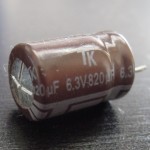
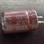
As you can tell from the pictures, the part is:
Manufactured by TK, max voltage 6.3V, capacitance 820uF, max operating temperature is 105 degrees Celsius, and it's from the ATWY series. 646A is a date code.
In most electronics repair situations you'd simply replace the broken capacitor with a new one of equal capacitance and the same or higher voltage rating. This part measured an ESR of less than 1.1 ohms, which for most circuits would indicate a healthy component. In modern computers however, specs are much tighter, and parts that would work perfectly in most circuits can make a computer fail.
A google search for "TK ATWY" led me to the data sheet, which revealed that this 6.3V, 820uF capacitor has an Impedance (other word for ESR) of 0.036ohms, and a max ripple current of 1140mA.
We're looking for a part with the following specs:
Capacitance: 820uF (this value must be identical to original part)
Voltage: 6.3V (this value can be equal or higher)
Temperature: 105C (look at the placement of the part; how hot will it get in that position? In this case, very close to the South Bridge; 105C or more is recommended)
Impedance/ESR: 0.036 ohms (this value must be equal or lower, but not too much lower)
Max Ripple current: 1140mA (this value can be equal or higher)
Physical dimmensions: Diameter: 8mm (just make sure the part you order will fit on the board)
Then simply make sure you get the polarity right, and the board should work again. If not, this means the failing capacitor probably blew other components as it went out of spec. In most cases, replacing the faulty capacitor(s) solves the problem.
After a repair like this it's probably a good idea to clear CMOS+RTC, just in case something got corrupted when the computer became unstable.
12AX7 comparison
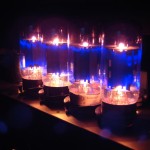
I decided to buy a selection of 12AX7 tubes to find out how they differ.
Remember to switch to 480p for better sound quality:
I tested the following tubes:
JJ ECC83 S
Shuguang 12AX7-B
old used chinese 12AX7A
Sovtek B
Sovtek LPS
Mullard Reissue
Svetlana Reissue
Tung-Sol Reissue
I tested the tubes by placing it in the V1 position, which is where 75% of the tone is made. the other 3 tubes (the last 25%) are Shugang 12AX7-B.
Settings on the rock master is ultra channel, gain pulled, max gain, EQ 3, -3, 3. The cabinet is close miced using an E906.
To get the same performance on all tracks I prerecorded a clip of dry guitar, and fed that to the rock master using a reamp box.
In my opinion, the differences between the tubes are negliable. It was however possible to reveal some difference by comparing two out of phase samples.
Tube mic build
 |
 |
 |
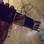 |
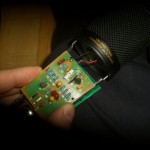
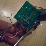
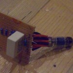
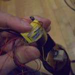
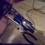
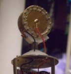
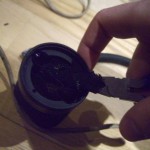
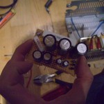
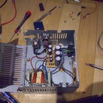
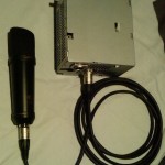
| Here's how to turn a $35 chinese large diaphragm condenser microphone into a high quality tube microphone. The result may not sound like a $10.000 U47, but it should be comparable to products in the $1.000 range. This mod is usually referred to as the "Royer Mod". It was designed by Dave Royer, and the original article can be found here: http://recordinghacks.com/articles/one-tube-microphone-from-berlin/ Capsule This mic uses a capsule (diaphragm) that is copied from the Neumann KK67/87 capsule, which was used in the Neumann U-67, U-87, SM-69 and M-269. And it is a pretty decent copy, it sounds very good! Head amplifier The head amplifier is where the problems start in this mic. The original circuit is not horribly bad, but it could be better. The circuit I built is similar to what is found in the Neumann U47, but modified to match the impedance of the capsule. As the tube in the U47 is very rare, it has been replaced by a more common 5840, which is electrically similar to the AC701K tube used in the Neumann M-49. I ended up using a 6205, which is a very similar tube. It's said to have less noise and higher shock tolerance, and it has a slightly different pinout compared to the 5840. Transformer The output transformer in the MXL 2001 is horrible, replacing this attributes to probably 50% of the improvement in sound quality. Replaced it with a Jensen DB/E. Power supply The tube requires about 100V DC to operate, and the 48V phantom power is far from sufficient. I built the power supply into the case of an old AT computer power supply. Keeping the power supply away from the head amp circuit is not only important due to size limitations within the mic, it is also crucial for eliminating noise. Head basket Like most cheap LDC's, this mic has too many layers of mesh obstructing the capsule. Manufacturers do this to protect the capsule, at the expense of sound quality. I got rid of one layer as a start, but should really get rid of one more. |
   |
 |
 |
 |
 |


